Mastering CAD for 3D Printing: Crafting Digital Perfection
Embarking on the journey of 3D printing is an exciting endeavor, and mastering Computer-Aided Design (CAD) is a pivotal step toward turning your creative ideas into tangible objects. With the right tools and resources, you can craft digital models that translate seamlessly into 3D-printed masterpieces. In this guide, we’ll explore top-rated CAD software and educational materials that can help you achieve digital perfection in your 3D printing projects.
Understanding the Importance of CAD in 3D Printing
Learning CAD for 3D Printing? You Need This.
CAD software serves as the bridge between your conceptual designs and the physical world of 3D printing. It allows you to create precise 3D models, define intricate geometries, and ensure that your designs are optimized for printing. Choosing the right CAD tool is crucial, as it influences the complexity of designs you can create and the efficiency of your workflow.
Top CAD Software for 3D Printing
Here are some highly-rated CAD software options that have garnered positive reviews and are popular among 3D printing enthusiasts:
Fusion 360 is a professional-grade CAD software that offers a comprehensive suite of tools for 3D modeling, simulation, and manufacturing. It’s known for its user-friendly interface and robust features, making it suitable for both beginners and advanced users. Fusion 360 supports parametric design, allowing you to make adjustments to your models easily. Additionally, it offers cloud-based collaboration, enabling you to work on projects with team members in real-time.
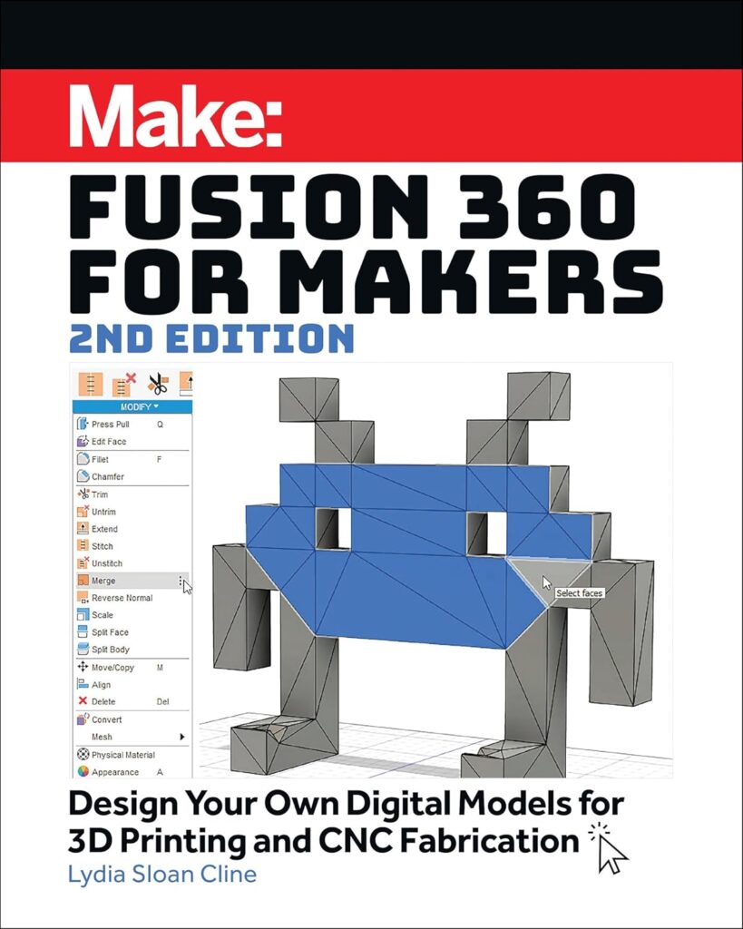
Fusion 360 – Beginners Guide
2. Onshape
Onshape is a cloud-based CAD platform that facilitates real-time collaboration. It’s accessible from any device with an internet connection, making it a flexible option for designers on the go. Onshape provides robust modeling tools and version control, ensuring that your design iterations are well-managed. Its intuitive interface and comprehensive tutorials make it a favorite among educators and professionals alike.
How Onshape’s Cloud Architecture Actually Works
3. Tinkercad
For those new to 3D design, Tinkercad offers an excellent starting point. Developed by Autodesk, this free, browser-based application provides a simple and intuitive interface that allows users to create 3D models using basic shapes and tools. Tinkercad is particularly popular in educational settings and among hobbyists looking to create straightforward designs without a steep learning curve.

TinkerCAD – Tutorial for Beginners in 9 minutes
DesignSpark Mechanical is a free 3D CAD software that combines the power of direct modeling with an easy-to-use interface. It’s designed to be intuitive, allowing users to quickly create and modify designs without the complexity found in some professional CAD programs. DesignSpark Mechanical is particularly well-suited for creating mechanical components and is favored by engineers and designers who require precision in their models.
The Best Free CAD Program – DesignSpark Mechanical
5. FreeCAD
FreeCAD is an open-source parametric 3D CAD modeler that is highly customizable and extensible. It’s suitable for a wide range of applications, including product design, mechanical engineering, and architecture. FreeCAD’s parametric modeling allows you to modify your designs by going back into your model history and changing its parameters. This feature is particularly useful for iterative design processes.
FreeCAD Review
Additional CAD Software Options
While the five options above are among the most popular, other CAD programs might suit your specific needs:
- SolidWorks – An industry-standard software for professional engineering and product design.
First Look – SOLIDWORKS CAD
- Blender – Primarily used for animation and rendering, but also has robust 3D modeling tools for printing.

Learn Blender for 3D Printing – Complete Guide
- SketchUp – A user-friendly tool great for architectural and simple 3D modeling.

Getting Started with SketchUp Pro 2025!
- Rhinoceros 3D – Excellent for freeform and organic modeling, popular in product design.

10 Reasons to use Rhino as your CAD Software
Educational Resources to Enhance Your CAD Skills
To effectively master CAD for 3D printing, it’s beneficial to supplement your software tools with educational resources. Here are some top-rated books that can guide you through the learning process:
1. “Getting Started with 3D Printing: A Hands-on Guide to the Hardware, Software, and Services Behind the New Manufacturing Revolution”
This book provides a comprehensive introduction to 3D printing, covering the essential hardware and software components. It’s designed for beginners and offers practical insights into the 3D printing ecosystem. Readers appreciate its clear explanations and step-by-step guidance, making it a valuable resource for those new to the field.
Make: Getting Started with 3D Printing
2. “3D Printing Made Easy for Newbies and Hobbyists: A Quick-Start Guide to Learn How to 3D Print at Home”
Aimed at newcomers to 3D printing, this book breaks down the process into easy-to-understand steps. It covers everything from setting up your printer to creating your first 3D model using accessible CAD software. Readers find it to be a helpful starting point that demystifies the complexities of 3D printing.
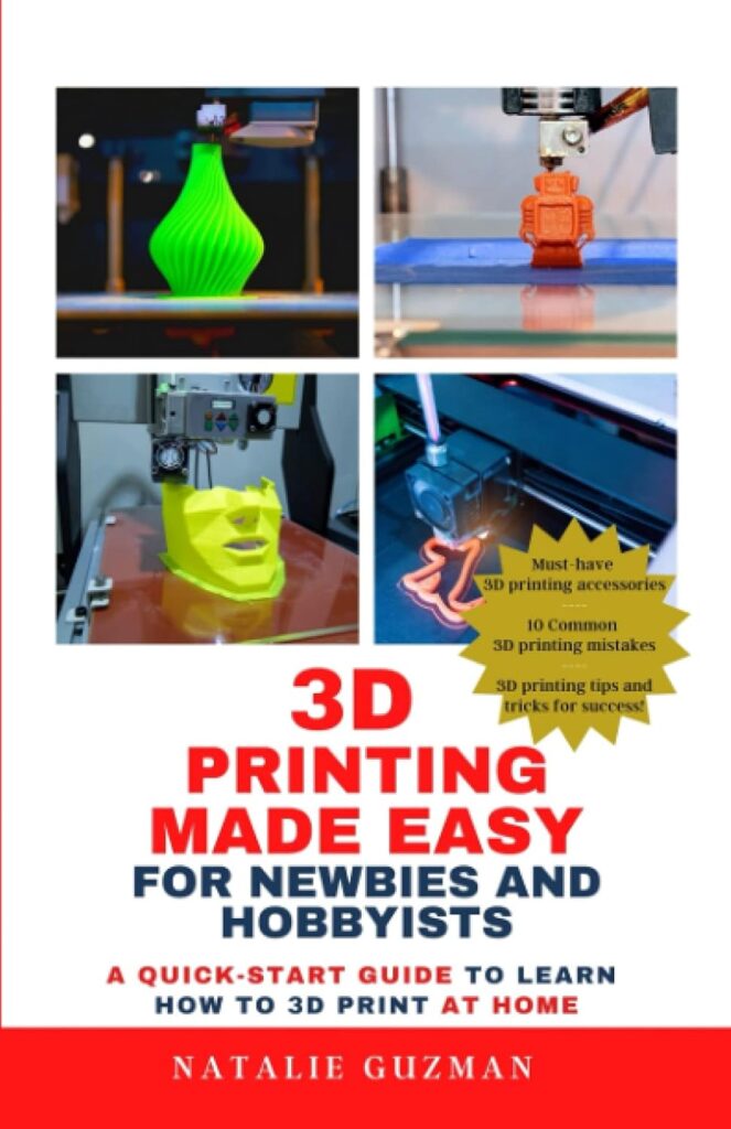
3D Printing Made Easy: Book Review
3. “3D Printing Without Prior Knowledge: 7 Days to Your First 3D Print”
This guide is structured as a seven-day course, leading readers from no prior knowledge to completing their first 3D print. It covers the basics of 3D modeling, slicing, and printing, providing a solid foundation for beginners. The book’s structured approach and clear instructions make it a popular choice for self-learners.

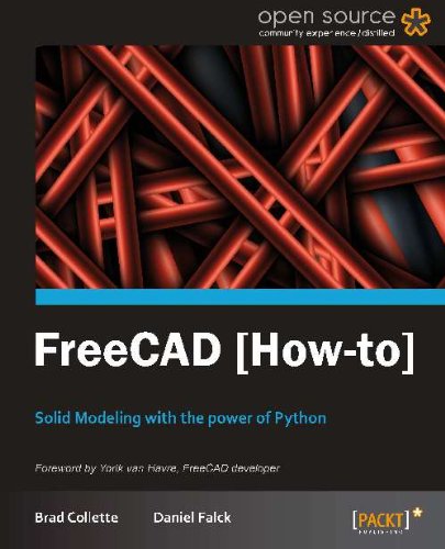
4. “FreeCAD [How-to]: Learn to Design 3D Objects with FreeCAD”
Focused on the open-source FreeCAD software, this book offers a practical approach to learning 3D design. It includes step-by-step tutorials that guide users through creating various models, helping them become proficient in using FreeCAD for 3D printing projects. Readers appreciate its hands-on approach and detailed explanations.
Conclusion
Mastering CAD for 3D printing is an empowering and rewarding process. By selecting the right software and investing in educational resources, you can develop the skills needed to transform your ideas into real-world objects. Whether you’re a beginner exploring Tinkercad or an advanced user diving into Fusion 360, there’s a CAD tool suited for your journey.
Best Design Program For 3D Printing!
As technology continues to evolve, 3D printing is becoming more accessible and versatile, offering endless possibilities for innovation. The key to success lies in practice, continuous learning, and experimentation. The more you refine your designs and push the limits of your creativity, the more you’ll master digital perfection.
If you’re ready to take your 3D printing skills to the next level, start exploring the recommended software and educational resources today. Happy designing and printing!